Table of Contents
- Introduction
- What is a Scrambler?
- Implementing Scramblers
- Optimising Fibonacci
- Benchmarks
- Conclusion
- Footnotes & References
Introduction
So for whatever reason, I’ve found myself implementing, in software, various scramblers used in telecommunications systems, specifically multiplicative Linear Feedback Shift Registers (LFSRs). Along the way, I came up with a potential optimisation for one class of scrambler, pitting it against more traditional implementations, with mixed results. TLDR: it depends on your compiler.
What is a Scrambler?
A scrambler is used in communications systems to reversibly make data look more “random”. There are various reasons one might want to do so:
- Random data tends to have lots transitions between
1’s and0’s, making clock recovery easier by eliminating long runs of repeated bits that could cause a receiver to loose track; or, - When modulating a signal, for example over radio frequency, a suitably scrambled payload “spreads” transmitted energy across the radio spectrum.
This is, however, distinct to encryption. While the properties of a suitably randomised data stream are useful from an engineering perspective, the manner in which they are applied is fairly easily recovered (at least compared to actual encryption).
The long and the short of it is that, scramblers turn this:
Into this (and back):

Aside: For radio signals that transmit more than 1-bit at a time through higher order modulation techniques (e.g. QPSK, n-FSK), a non-randomised payload could be catastrophic for the receiver. This is particularly so when the payload is highly structured, as would be case for idling digital carriers such as HDLC (packet data, with an repeated idle of
0x7e), or A-Law (voice data, idle of0x54). The signal could appear to be a lower order than what it actually is (or be really weird and look like 3PSK which as far as I know doesn’t actually exist) because not all possible “symbols” are ever transmitted.
Linear Feedback Shift Registers
Scramblers of this nature are commonly implemented using Linear Feedback Shift Registers (LFSRs), which, in and of themselves, produce pseudo-random binary sequences (PRBSs). They are essentially a series of “cells” that store a single bit, and are shifted in a single direction every clock cycle. The input to the cells is a function of values already in the register at specific points called “taps”, hence the term “feedback”.
They are described in terms of the following:
- Their taps – which cells provide feedback to the input;
- Their length or degree – how many cells the LFSR has, this is determined by the position of the highest tap;
- Their state – what values are in the register at any given time.
The choice of taps are massively important, as they determine the overall length of the generated PRBS. The maths of which are a bit beyond me, but an ideal set of taps won’t repeat its sequence until $2^{degree} - 1$ clock cycles have occurred.
As an example, I’ve prepared an animation of a scrambling LFSR with taps at
cells 5 and 6. At every clock cycle, a zero is XORed with the values at each
tap and then inserted into the register on the left hand side, shifting the
existing values to the right. We can also say that:
- the length (or degree) of the register is $6$; and,
- the starting state is all
1s.
This arrangement will cycle the register through every one of it’s possible “legal” state of the register, which in this case is indeed $2^{degree} - 1$.
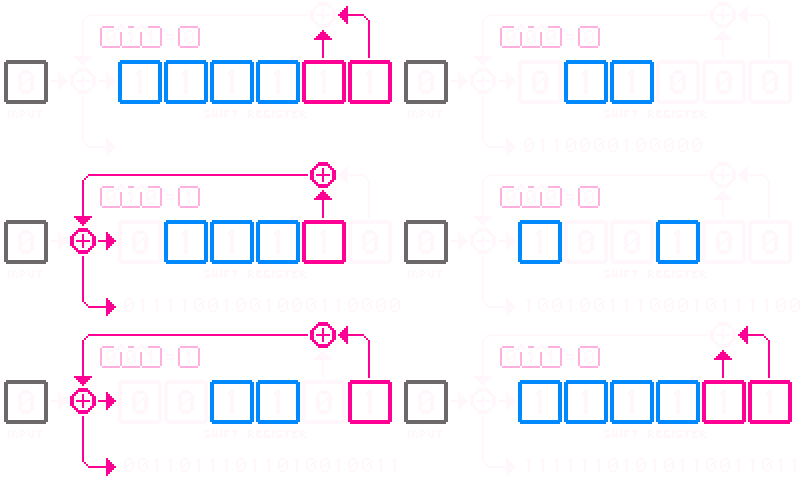
Aside: The notation describing an LFSR is given by polynomials. The above animation could be said to have a polynomial of $x^6 + x^5 + 1$, where the exponents indicate the tap positions, and the $1$ indicates the input. Ultimately, this is where the term “degree” comes from; the degree of a polynomial is the highest degree of the polynomial1.
A Taxonomy of Scramblers
There are two types of scrambler: additive and multiplicative.
-
An additive scrambler applies a separately generated PRBS to a stream of data. This will be done via inserting a frame alignment sequence (a.k.a. a sync-word), after which the PRBS will be XORed with the data at a given specific starting register state. The PRBS will typically be truncated to some frame length.
-
A multiplicative scrambler combines incoming data bits with the taps, and inserts the modified bit into the register. The animation above is an example of such a scrambler. This type has a really interesting property; when descrambling, if you don’t know a priori the state of the register, but you know the taps, the output will eventually sort itself out. In the worst case this will initially output garbage up until ${degree}$ clock cycles.
Furthermore, there are two “configurations” of LFSR, Galois and Fibonacci. These are eponymously named after Évariste Galois and Leonardo Fibonacci.
- In Fibonacci arrangement, the tap positions are sampled directly and XORed together to produce the next bit, i.e., a tap sample is fed outside of the register and combined with samples from the other taps.
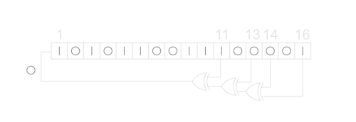
- In a Galois arrangement, a “tap” samples a previous cell and the “output” bit, XORing them together, and then feeds the next cell in the register.

I will be ignoring additive scramblers. While useful, they’re fairly straightforward and have an entirely predictable performance profile: the PRBS can be calculated in advance and simply XORed with input data, making it not particularly interesting from an optimisation perspective.
Implementing Scramblers
I wanted to see how, in practice, both configurations (of the multiplicative type) would perform compared to one another if we gave the compiler every chance to optimise them. Galois LFSRs are apparently favoured in software implementations2 as they can calculate all the tap contributions in one go. Let’s see if this pans out.
The scramblers are implemented at GitHub: CommitThis/lfsr-scramblers.
They are all implemented in C++ terms of a std::bitset
as it makes the bit operations extremely ergonomic, e.g., we don’t need to
worry about mask and carry3. Additionally, all of the
implementations are templated on their taps. This allows the compiler to know
the length of the registers, and positions of the taps statically, potentially
favouring hypothetical optimisations.
Templating them in this manner is less convenient if you want to create aribtrary LFSRs, as you would have to declare them in advance.
The standard implementations have a utility/traits class defined that gives us the “static” information for a given set of taps, universal to both Fibonacci and Galoi configurations:
template <std::size_t ... Taps>
struct lfsr_traits
{
    using tap_list = detail::make_tap_list_t<Taps...>;

    constexpr static auto degree = std::max({Taps...});
    constexpr static auto tap_indices = tap_list::to_indices::values;

    using buffer_type = std::bitset<degree>;

    /* For intialising buffer state to 0 */
    static auto all_ones() -> buffer_type
    { return buffer_type{}.set(); }
};
The tap indices are a transformed array of taps, converted to a zero
indexed form that makes it more convenient to use as an offset within a
std::bitset, and additionally has the $0th$ tap removed. E.g., given taps
$0, 4, 10, 11, 12$, the indices would be $3, 9, 10, 11$. The reason for this is
that the $0th$ tap is symbolic; it represents the input bit and is not
ordinarily a part of the shift register (foreshadowing intensifies).
Hereby is the core part of the Fibonacci configuration:
template <std::size_t ... Taps>
class feedthrough_fibonacci
{
public:
    using traits = lfsr_traits<Taps...>;
    using buffer_type = typename traits::buffer_type;

    feedthrough_fibonacci()
        : m_buffer{traits::all_ones()}
    {}

    auto scramble_bit(bool input) noexcept -> bool {
        for (auto t : traits::tap_indices) {
            input ^= this->m_buffer.test(t);
        }
        this->m_buffer <<= 1;
        this->m_buffer.set(0, input);
        return input;
    }

    auto descramble_bit(bool input) noexcept -> bool {
        auto result = input;
        for (auto t : traits::tap_indices) {
            result ^= this->m_buffer.test(t);
        }
        this->m_buffer <<= 1;
        this->m_buffer.set(0, input);
        return result;
    };

    buffer_type m_buffer;
};
And the Galois:
template <std::size_t ... Taps>
class feedthrough_galois
{
public:
    using traits = lfsr_traits<Taps...>;
    using buffer_type = typename traits::buffer_type;

    feedthrough_galois()
        : m_buffer{traits::all_ones()}
        , m_taps{}
    {
        for (auto t : traits::tap_indices) {
            this->m_taps.set(t);
        }
    }

    auto scramble_bit(bool input) noexcept -> bool {
        auto out = this->m_buffer.test(0) ^ input;
        this->m_buffer >>= 1;
        if (out) {
            this->m_buffer ^= this->m_taps;
        }
        this->m_buffer.set(traits::degree - 1, out);
        return out;
    }

    auto descramble_bit(bool input) noexcept -> bool {
        auto out = this->m_buffer.test(0) ^ input;
        this->m_buffer >>= 1;
        if (input) {
            this->m_buffer ^= this->m_taps;
        }
        this->m_buffer.set(traits::degree - 1, input);
        return out;
    };

    buffer_type m_buffer;
    buffer_type m_taps;
};
Theoretically speaking, without considering compiler magic, it should be obvious that the complexity of a Fibonacci LFSR will grow relative to the number of taps (and their degree, by virtue of the underlying storage), the Galois LFSR is dependent only on the degree.
The implementations on GitHub also have functions to process a byte at a time, which is definitely more convenient for dealing with raw data. This is done by iterating over each of the bits in a byte in turn. There are also functions similarly implemented for ranges of bytes, using iterators.
Note: While different “configurations” of multiplicative scramblers for a given tap sequence are “universal” (e.g. a Galois LFSR can descramable a sequence of bytes scrambled by a Fibonacci LFSR.. eventually), this is only true so long as the bits are iterated across in the same order. This is particularly relevant if you want to keep a mental model of how these work.
Optimising Fibonacci
So one might consider an optimisation for the Fibonacci configuration to work on bytes at a time by unrolling the loop and some bit twiddling.
As a starting point, lets extend our register to also include the input bits, in
this case, up to the size of a byte. Those familiar with bit twiddling might
realise that we can calculate the feedback value for a given bit by ANDing the
combined register with a mask populated with 1’s at the tap positions and
getting the population count (the number of bits set) $mod 2$.
It follows that we could create a set of masks, shifted in time, and apply them to each bit in turn. The following table describes such an arrangement where:
- $I_{n}$ represents the input byte portion of the register; and,
- $R_{n}$ represents the state portion of the register; and,
- A pink
1indicates an input bit; and, - A blue
1indicates a dependency bit.
| Bit | $I_{7}$ | $I_{6}$ | $I_{5}$ | $I_{4}$ | $I_{3}$ | $I_{2}$ | $I_{1}$ | $I_{0}$ | $R_{5}$ | $R_{4}$ | $R_{3}$ | $R_{2}$ | $R_{1}$ | $R_{0}$ |
|---|---|---|---|---|---|---|---|---|---|---|---|---|---|---|
0 |
$\color{#bbbbbb}{0}$ | $\color{#bbbbbb}{0}$ | $\color{#bbbbbb}{0}$ | $\color{#bbbbbb}{0}$ | $\color{#bbbbbb}{0}$ | $\color{#bbbbbb}{0}$ | $\color{#bbbbbb}{0}$ | $\color{#f147ab}{1}$ | $\color{#bbbbbb}{0}$ | $\color{#bbbbbb}{0}$ | $\color{#bbbbbb}{0}$ | $\color{#bbbbbb}{0}$ | $\color{#559cff}{1}$ | $\color{#559cff}{1}$ |
1 |
$\color{#bbbbbb}{0}$ | $\color{#bbbbbb}{0}$ | $\color{#bbbbbb}{0}$ | $\color{#bbbbbb}{0}$ | $\color{#bbbbbb}{0}$ | $\color{#bbbbbb}{0}$ | $\color{#f147ab}{1}$ | $\color{#bbbbbb}{0}$ | $\color{#bbbbbb}{0}$ | $\color{#bbbbbb}{0}$ | $\color{#bbbbbb}{0}$ | $\color{#559cff}{1}$ | $\color{#559cff}{1}$ | $\color{#bbbbbb}{0}$ |
2 |
$\color{#bbbbbb}{0}$ | $\color{#bbbbbb}{0}$ | $\color{#bbbbbb}{0}$ | $\color{#bbbbbb}{0}$ | $\color{#bbbbbb}{0}$ | $\color{#f147ab}{1}$ | $\color{#bbbbbb}{0}$ | $\color{#bbbbbb}{0}$ | $\color{#bbbbbb}{0}$ | $\color{#bbbbbb}{0}$ | $\color{#559cff}{1}$ | $\color{#559cff}{1}$ | $\color{#bbbbbb}{0}$ | $\color{#bbbbbb}{0}$ |
3 |
$\color{#bbbbbb}{0}$ | $\color{#bbbbbb}{0}$ | $\color{#bbbbbb}{0}$ | $\color{#bbbbbb}{0}$ | $\color{#f147ab}{1}$ | $\color{#bbbbbb}{0}$ | $\color{#bbbbbb}{0}$ | $\color{#bbbbbb}{0}$ | $\color{#bbbbbb}{0}$ | $\color{#559cff}{1}$ | $\color{#559cff}{1}$ | $\color{#bbbbbb}{0}$ | $\color{#bbbbbb}{0}$ | $\color{#bbbbbb}{0}$ |
4 |
$\color{#bbbbbb}{0}$ | $\color{#bbbbbb}{0}$ | $\color{#bbbbbb}{0}$ | $\color{#f147ab}{1}$ | $\color{#bbbbbb}{0}$ | $\color{#bbbbbb}{0}$ | $\color{#bbbbbb}{0}$ | $\color{#bbbbbb}{0}$ | $\color{#559cff}{1}$ | $\color{#559cff}{1}$ | $\color{#bbbbbb}{0}$ | $\color{#bbbbbb}{0}$ | $\color{#bbbbbb}{0}$ | $\color{#bbbbbb}{0}$ |
5 |
$\color{#bbbbbb}{0}$ | $\color{#bbbbbb}{0}$ | $\color{#f147ab}{1}$ | $\color{#bbbbbb}{0}$ | $\color{#bbbbbb}{0}$ | $\color{#bbbbbb}{0}$ | $\color{#bbbbbb}{0}$ | $\color{#559cff}{1}$ | $\color{#559cff}{1}$ | $\color{#bbbbbb}{0}$ | $\color{#bbbbbb}{0}$ | $\color{#bbbbbb}{0}$ | $\color{#bbbbbb}{0}$ | $\color{#bbbbbb}{0}$ |
6 |
$\color{#bbbbbb}{0}$ | $\color{#f147ab}{1}$ | $\color{#bbbbbb}{0}$ | $\color{#bbbbbb}{0}$ | $\color{#bbbbbb}{0}$ | $\color{#bbbbbb}{0}$ | $\color{#559cff}{1}$ | $\color{#559cff}{1}$ | $\color{#bbbbbb}{0}$ | $\color{#bbbbbb}{0}$ | $\color{#bbbbbb}{0}$ | $\color{#bbbbbb}{0}$ | $\color{#bbbbbb}{0}$ | $\color{#bbbbbb}{0}$ |
7 |
$\color{#f147ab}{1}$ | $\color{#bbbbbb}{0}$ | $\color{#bbbbbb}{0}$ | $\color{#bbbbbb}{0}$ | $\color{#bbbbbb}{0}$ | $\color{#559cff}{1}$ | $\color{#559cff}{1}$ | $\color{#bbbbbb}{0}$ | $\color{#bbbbbb}{0}$ | $\color{#bbbbbb}{0}$ | $\color{#bbbbbb}{0}$ | $\color{#bbbbbb}{0}$ | $\color{#bbbbbb}{0}$ | $\color{#bbbbbb}{0}$ |
It might be obvious why this won’t work. Everything is fine up until input bit 5. They depend on other input bits! This is the feedback nature of the LFSR at play: we can’t calculate feedback for input bits 5 and up without previously having calculated the value for those other input bits.
- For input bit
6, we need input bit0; and, - For input bit
7, we need input bits1and0; and, - For input bit
8, we need input bits2and1.
However, all is not lost.
If we calculate the masks (in this arrangement) for every bit in the input from right to left, every time we encounter an input bit with a dependency on another input bit, we can simply XOR the other’s dependency mask with the current. This reveals a set of masks that looks as follows:
| Bit | $I_{7}$ | $I_{6}$ | $I_{5}$ | $I_{4}$ | $I_{3}$ | $I_{2}$ | $I_{1}$ | $I_{0}$ | $R_{5}$ | $R_{4}$ | $R_{3}$ | $R_{2}$ | $R_{1}$ | $R_{0}$ |
|---|---|---|---|---|---|---|---|---|---|---|---|---|---|---|
0 |
$\color{#bbbbbb}{0}$ | $\color{#bbbbbb}{0}$ | $\color{#bbbbbb}{0}$ | $\color{#bbbbbb}{0}$ | $\color{#bbbbbb}{0}$ | $\color{#bbbbbb}{0}$ | $\color{#bbbbbb}{0}$ | $\color{#f147ab}{1}$ | $\color{#bbbbbb}{0}$ | $\color{#bbbbbb}{0}$ | $\color{#bbbbbb}{0}$ | $\color{#bbbbbb}{0}$ | $\color{#559cff}{1}$ | $\color{#559cff}{1}$ |
1 |
$\color{#bbbbbb}{0}$ | $\color{#bbbbbb}{0}$ | $\color{#bbbbbb}{0}$ | $\color{#bbbbbb}{0}$ | $\color{#bbbbbb}{0}$ | $\color{#bbbbbb}{0}$ | $\color{#f147ab}{1}$ | $\color{#bbbbbb}{0}$ | $\color{#bbbbbb}{0}$ | $\color{#bbbbbb}{0}$ | $\color{#bbbbbb}{0}$ | $\color{#559cff}{1}$ | $\color{#559cff}{1}$ | $\color{#bbbbbb}{0}$ |
2 |
$\color{#bbbbbb}{0}$ | $\color{#bbbbbb}{0}$ | $\color{#bbbbbb}{0}$ | $\color{#bbbbbb}{0}$ | $\color{#bbbbbb}{0}$ | $\color{#f147ab}{1}$ | $\color{#bbbbbb}{0}$ | $\color{#bbbbbb}{0}$ | $\color{#bbbbbb}{0}$ | $\color{#bbbbbb}{0}$ | $\color{#559cff}{1}$ | $\color{#559cff}{1}$ | $\color{#bbbbbb}{0}$ | $\color{#bbbbbb}{0}$ |
3 |
$\color{#bbbbbb}{0}$ | $\color{#bbbbbb}{0}$ | $\color{#bbbbbb}{0}$ | $\color{#bbbbbb}{0}$ | $\color{#f147ab}{1}$ | $\color{#bbbbbb}{0}$ | $\color{#bbbbbb}{0}$ | $\color{#bbbbbb}{0}$ | $\color{#bbbbbb}{0}$ | $\color{#559cff}{1}$ | $\color{#559cff}{1}$ | $\color{#bbbbbb}{0}$ | $\color{#bbbbbb}{0}$ | $\color{#bbbbbb}{0}$ |
4 |
$\color{#bbbbbb}{0}$ | $\color{#bbbbbb}{0}$ | $\color{#bbbbbb}{0}$ | $\color{#f147ab}{1}$ | $\color{#bbbbbb}{0}$ | $\color{#bbbbbb}{0}$ | $\color{#bbbbbb}{0}$ | $\color{#bbbbbb}{0}$ | $\color{#559cff}{1}$ | $\color{#559cff}{1}$ | $\color{#bbbbbb}{0}$ | $\color{#bbbbbb}{0}$ | $\color{#bbbbbb}{0}$ | $\color{#bbbbbb}{0}$ |
5 |
$\color{#bbbbbb}{0}$ | $\color{#bbbbbb}{0}$ | $\color{#f147ab}{1}$ | $\color{#bbbbbb}{0}$ | $\color{#bbbbbb}{0}$ | $\color{#bbbbbb}{0}$ | $\color{#bbbbbb}{0}$ | $\color{#559cff}{1}$ | $\color{#559cff}{1}$ | $\color{#bbbbbb}{0}$ | $\color{#bbbbbb}{0}$ | $\color{#bbbbbb}{0}$ | $\color{#559cff}{1}$ | $\color{#559cff}{1}$ |
6 |
$\color{#bbbbbb}{0}$ | $\color{#f147ab}{1}$ | $\color{#bbbbbb}{0}$ | $\color{#bbbbbb}{0}$ | $\color{#bbbbbb}{0}$ | $\color{#bbbbbb}{0}$ | $\color{#559cff}{1}$ | $\color{#559cff}{1}$ | $\color{#bbbbbb}{0}$ | $\color{#bbbbbb}{0}$ | $\color{#bbbbbb}{0}$ | $\color{#559cff}{1}$ | $\color{#bbbbbb}{0}$ | $\color{#559cff}{1}$ |
7 |
$\color{#f147ab}{1}$ | $\color{#bbbbbb}{0}$ | $\color{#bbbbbb}{0}$ | $\color{#bbbbbb}{0}$ | $\color{#bbbbbb}{0}$ | $\color{#559cff}{1}$ | $\color{#559cff}{1}$ | $\color{#bbbbbb}{0}$ | $\color{#bbbbbb}{0}$ | $\color{#bbbbbb}{0}$ | $\color{#559cff}{1}$ | $\color{#bbbbbb}{0}$ | $\color{#559cff}{1}$ | $\color{#bbbbbb}{0}$ |
We can see that additional dependencies can be seen in the bottom right of the table. The zeroes in the pattern occur because it means a dependency was specified some multiple of two. If this happens, the dependency is cancelled out.
Note: The descrambling dependencies is the naive dependency list. The input bits are being inserted into the LFSR unchanged, and therefore the output is solely dependent on existing input bits, no feedback is calculated. Another way of looking at it is that the dependencies are already “baked in” to the input stream.
I’m not going to include all the code for the “bulk” LFSR here, but will outline some of the important parts.
We will still have a traits class, with some extra bits:
template <std::size_t ... Taps>
struct lfsr_bulk_traits
{
    constexpr static auto degree = std::max({Taps...});
    constexpr static auto buffer_size = degree + CHAR_BIT;

    using tap_list        = detail::make_tap_list_t<Taps...>;
    using buffer_type     = std::bitset<buffer_size>;
    using dependency_list = std::array<buffer_type, char_bits>;

    static auto all_ones() -> buffer_type;
    static auto scramble_dependencies() -> dependency_list;
    static auto descramble_dependencies() -> dependency_list;
};
Then, instead of providing a scramble_bit function,
we write a scramble_byte function that performs the
mask and population count for each bit:
template <std::size_t ... Taps>
class feedthrough_fibonacci_bulk
{
public:
    using traits          = lfsr_bulk_traits<Taps...>;
    using buffer_type     = typename traits::buffer_type;
    using dependency_list = typename traits::dependency_list;

    feedthrough_fibonacci_bulk()
        : m_buffer{traits::all_ones()}
        , m_deps_scramble{traits::scramble_dependencies()}
        , m_deps_descramble{traits::descramble_dependencies()}
    {
    }

    auto scramble_byte(std::uint8_t value) -> std::uint8_t
    {
        const static auto setmask = traits::state_mask();
        m_buffer >>= 8;
        m_buffer |= (buffer_type{value} << degree);

        auto result = std::uint8_t{};
        result |= ((m_buffer & m_deps_scramble[0]).count() & 1) << 0;
        result |= ((m_buffer & m_deps_scramble[1]).count() & 1) << 1;
        result |= ((m_buffer & m_deps_scramble[2]).count() & 1) << 2;
        result |= ((m_buffer & m_deps_scramble[3]).count() & 1) << 3;
        result |= ((m_buffer & m_deps_scramble[4]).count() & 1) << 4;
        result |= ((m_buffer & m_deps_scramble[5]).count() & 1) << 5;
        result |= ((m_buffer & m_deps_scramble[6]).count() & 1) << 6;
        result |= ((m_buffer & m_deps_scramble[7]).count() & 1) << 7;

        m_buffer = (m_buffer & setmask) | (buffer_type{result} << degree);
        return result;
    }
private:
    buffer_type     m_buffer;
    dependency_list m_deps_descramble;
    dependency_list m_deps_scramble;
};
Benchmarks
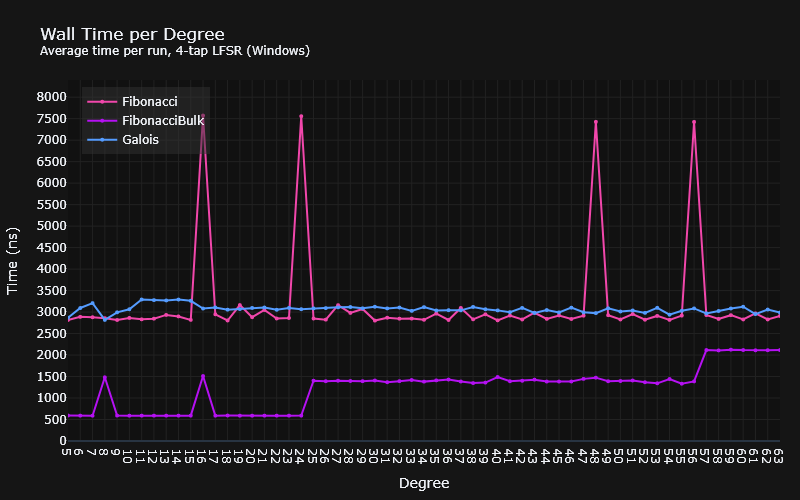
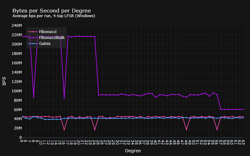
Benchmarks were implemented for every 4-tap LFSR listed in tables published by the University of Otago4, from degree 5, up to degree 63. Each run was performed by scrambling 128 bytes for as long as Google benchmark thought it was necessary.
According to the benchmarks, there are substantially different results across MSVC and GCC. On Linux, GCC produces significantly faster bit-by-bit LFSRs than MSVC, with the Galois version being the fastest, and the bulk Fibonacci disappointingly sitting just about faster than the ordinary Fibonacci. On Windows, however, the bulk Fibonacci version blows everybody out of the water. The disappointment here lies in the bit-by-bit versions, which are considerably slower than their Linux counterparts.
Note: Wall time (or real time) was used as the basis of these measurements. Using CPU time on Windows gave results that could not be correlated with the wall clock, and basically looked like garbage. I believe that this is down to the benchmark library using
GetThreadTimeor something, which has terrible accuracy for measuring small intervals of time.
Windows (MSVC)
Linux (WSL2 + GCC)
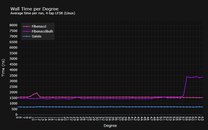
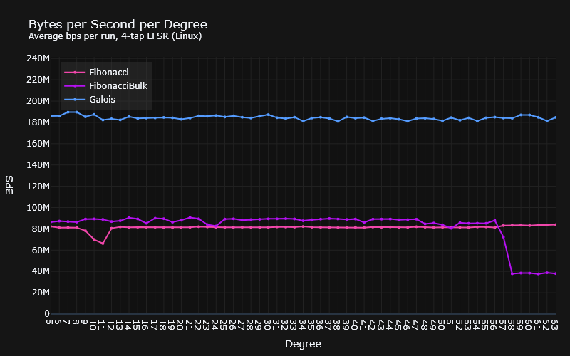
While I can’t explain the spikes and dips, I might be able to explain the staircase effect the bulk LFSRs have on Windows, and maybe Linux as well.
We could suppose that if we were implementing a std::bitset we could do so
using some internal primitive, like an unsigned integer type. If the bitset was
larger than the number of bits in this type, we could simply use multiple of
them in an array. The size (in bits) of this primitive would then determine when
we would need to do carries between them, when shifting in either direction.
This would add some constant overhead to the shift.
Indeed, the degree at which the steps occur on Windows could coincide with this. Remember that the bulk LFSR has a bitset size that is the degree + the size of a byte in bits. With the steps at degree 25 (33 bits), and degree 57 (65 bits) one might conclude that this is exactly what’s happening and that it uses a 32-bit primitive.
As for Linux, well, we could theorise it uses a 64-bit primitive, but I’d like to run the benchmarks past degree 120 to get a better picture. Especially given the disparity in results, and the fact that the drop off happens 1 degree later than expected. If the theory holds true, we should see a step around about there.
Or, you know, I could try and read the standard library code rather than guessing.
Conclusion
I had initially run the benchmarks on Windows, and consequently was quite surprised and impressed by the performance improvement over the traditional implementations, obviously not knowing how the Linux/GCC results would fare.
This surprise was then equalled in disappointment.
In fact, I very nearly walked away from this adventure with the wrong impression; initially I had only chosen to benchmark 1 specific set of taps ($x^{12} + x^{11} + x^{10} + x^{4} + {1}$). If I had done so, we wouldn’t have seen the interesting step pattern in the bulk LFSR, and that it drops off in performance with a much larger degree. Moral of the story: don’t assume that just because something works well in one specific set of circumstances, doesn’t make it true for every circumstance.
So, what else have we learned?
- GCC has better optimisations for these implementations;
- A “bulk” Fibonacci LFSR is definitely an option on Windows;
- the Galois LFSR has the most predictable performance, albeit slower on Windows.
That’s all for now. Maybe I’ll write my own bitset class, maybe throw in some
SIMD5? or maybe not.
Footnotes & References
-
Wikipedia: Degree of a polynomial ↩
-
Wikipedia: Galois LFSRs ↩
-
An container of bits of arbitrary length will require some fundamental underlying type (most likely some
unsignedtype), and if the container is big enough, it will require multiple of them. In order to perform shift operations, a mask and carry will be required. For example, a container of 16 bits using an 8 bit fundamental with the contents[0b00000111, 0b00000000], with a shift to the right of three bits will require that:a[1] = ((a[0] & 0x07) << 5) | (a[1] >> 3)a[0] = a[0] >> 3
-
University of Otago: Table of Linear Feedback Shift Registers ↩
-
Wikipedia: Single Instruction, Multiple Data ↩